Development of Antennas
History of Antennas
At the end of the 19th century scientists started conducting first experiments with antennas. It took several years until they learned how the design of an antenna influences characteristics such as the directivity of the antenna’s emittance and reception. In the 1920s, by combining simple dipole antennas, with their relatively broad directivity and small bandwidth, Yagi and Uda developed the classic TV antenna with its narrow directivity.

The detailed knowledge about antenna design and how it influences the bandwidth and emission pattern lead to tremendous technological advances. The wide distribution of radio transmitters and receivers in the 1930s and the success of television would not have been possible without antennas. Nowadays, antenna design is a standard discipline in electrical engineering and is indispensable in our lives. They continue to be optimized for mobile phones or wireless computer networks and have become cornerstones of our modern information society.
Modern Antennas
The principle design parameter of an antenna is its size. To be in resonance with the electromagnetic waves it is supposed to receive or transmit it should be approximately of the size of the wavelength. The fact that the antenna in a mobile phone is much smaller than a rooftop television antenna stems from the usage of shorter wavelengths. The advantage of shorter wavelengths and corresponding higher carrier frequencies is the possibility to transmit more information per time.
Optical Antennas
The technical advancement of the last decades made it possible to manufacture smaller and smaller structures. With the development of nanotechnology various methods (i. e. chemical growth, focussed ion beam milling (FIB) or electron beam (e-beam) lithography) made it possible to fabricate antennas small enough to shift their resonance wavelength into the part of the electromagnetic spectrum we usually refer to as light. Today, theses new antennas are often called “optical antennas”.
Difference of Optical Antennas
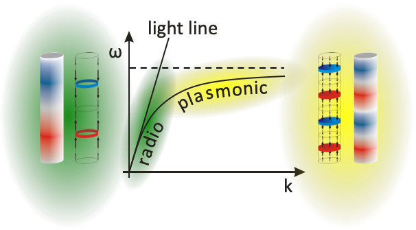
However, optical antennas seem to behave fundamentally different. While in normal antennas the wavelength of the metal part of the antenna is the same as the wavelength of the radiation in vacuum, this is not the case for optical antennas anymore. With frequencies approaching the optical regime, metals are not behaving like perfect conductors anymore and the ratio between frequency and wavelength is deviating from the "light line". We are entering the plasmonic regime.
Resonances of Optical Antennas
As a consequence, resonances of optical antennas are not appearing at odd numbered multiples of the vacuum wavelength but at much shorter antenna lengths. For simple dipole antennas, the resonances appear at approximately half the plasmon wavelength. With the plasmon wavelength being a fraction of the vacuum wavelength, antennas of sizes of little more than 100 nm become resonant to light in the infrared regime (800 nm).
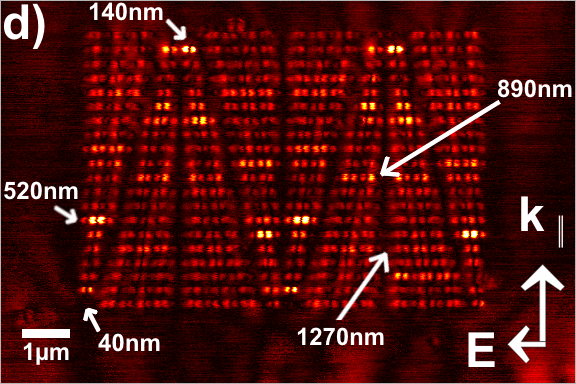
While the above shown dipole antennas have been stimulated at infrared wavelength longer than 800 nm, the dipole resonance appears at 140 nm which is shorter than λ/5. The image also shows higher order resonances, i.e., the 3/2 λ resonance at 520 nm, the 5/2 λ resonance at 890 nm and the 7/2 λ resonance at 1270 nm.
Emission of Optical Antennas
This mismatch between plasmon wavelength and vacuum wavelength has a fundamental influence on the radiation characteristics of the antennas. The simplest cas is the emission pattern of linear antennas. These can still be easily modeled by mathematical equations.
With the aid of a mathematical model of antenna characteristics of linear antennas, we can simulate how the emission and reception characteristics of the antenna behaves when an antenna is getting more and more plasmonic. While the normal antenna shows a strong lobe to the top and the bottom (green lines) in a 7/2 λ antenna, they disappear the more plasmonic the antenna gets. The plasmonic antenna resonant to the 7/2 λ excitation (λ being the plasmon wavelength in this case) shows only three emission lobes and resembles more the emission pattern of a 3/2 λ antenna.
Experimental Investigation of Optical Antennas
Detecting Optical Antennas
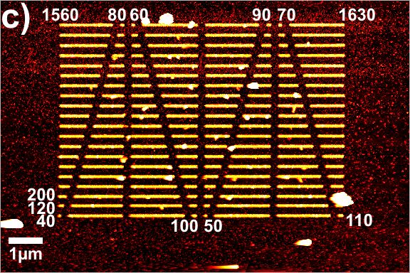
Unfortunately, optical antennas are too small to plug in a cable to detect the received radiation energy directly. To measure the resonances, the best way is to use a near-field microscope.
In an apertureless Scanning Near-Field Optical microscope, a sharp tip of an atomic force microscope is scanned over the optical antenna. Each time the tip enters the near-field around the antennas, light is scattered into the far-field and can be detected by an optical microscope. In general, the better the reception of the antenna is, the stronger are the near-fields and the stronger the intensity of the scattered light.
Detecting Complex Optical Antennas
In the meantime, research has advanced and scientists are able to build complexer antenna structures. For example, by electron lithography the plasmonic equivalent of the Yagi-Uda Antenna (well known as directional antenna for TV reception on many roofs) can be created.
Investigating this Yagi-Uda antenna with a sharp tip of a near-field microscope reveals that it works exactly the same way as a radio-frequency Yagi-Uda antenna does.
First the two shorter antenna elements, the directors, light up. Shortly after that, the receptor element shows the highest near-field intensity. Lastly, the longest element, the reflector lights up. The phase difference between directors and reflector is nearly 180°.